|
ÂÂ
ÂÂ
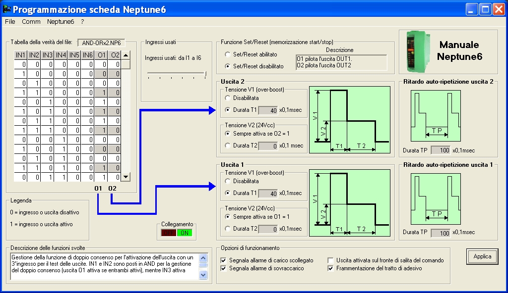
The NEPTUNE6-COM software is used to set the operating parameters and the configurations in the NEPTUNE6 driver on a PC, so that the data saved in it can be saved on disk or the data loaded on disk can be sent to it. Programming is performed via a PC with serial port RS232.
You can set the following data using the NEPTUNE6-COM software:
- Truth table that binds the status of the inputs to the 2 outputs
- Set the required operating mode (Set/Reset and trigger mode)
- Enable/disable control over the load current
- Set the times on the outputs
- Save the parameters read by NEPTUNE6 on disk
- Send the data loaded on disk to NEPTUNE6
- Test the inputs and outputs. Measure the temperature in the driver
ÂÂ
NEW FUNCTION
With the new software version for the new NEPTUNE6 with firmware V2.0 you can enable/disable the fragmenting function of the adhesive section.
Minimum system requirements:
- Operating system: Windowsâ„¢ 95, 98 , ME ,NT4, 2000, XP
- Computer: 100% Windowsâ„¢ compatible with serial port RS232
- CPU: 200MHz or superior
Windowsâ„¢ is a registered trade mark owned by Microsoft Corporation
Below are examples of configuring and using the NEPTUNE6 driver. The library contains examples of configuration files for NEPTUNE6:
ÂÂ
Files included in the library:
FILE NAME
|
CONFIGURATION DESCRIPTION
|
| AND-OR.np6 |
Management of a system where the output is activated by the simultaneous presence of 2 signals sent from a piece validity control PLC (connected on IN1) and from a cam controller (connected in IN2). To test the output, there is a dedicated test input (IN3) that activates the output despite the status of the inputs IN1 and IN2. |
| AND-ORx2.np6 |
Management of the double enabling signal function to activate the output with a third input to test the outputs. IN1 and IN2 are set in AND to manage the double enabling signal (output O1 active if both active), while IN3 activates output O1 despite the status of IN1 and IN2 to test the system. The inputs IN4, IN5 and IN6 perform on O2 the same function as IN1-IN3 (IN4 and IN5 for the double enabling signal and IN6 for the test). Each time the output is activated, an over-boost pulse is generated first of 4msec, then the voltage settles at 24V until the condition that keeps the output active is eliminated. |
auto_rpt.np6
|
Each output is associated with an activation input. Each time the input activates, the corresponding output generates an over-boost pulse of 4msec followed by a 24V pulse of 13msec. At the end of the time, the output switches back to pause to wait for a new pulse on the input. The timing of the output is constant even when the duration of the input pulse varies. |
| frenofrizione.np6 |
Management of an electro-magnetic brake/clutch unit. The brake is connected to -O (output 2), the clutch to O (output 1). IN1 is the start, IN2 is the stop, IN3 is the phase reading photocell and IN4 enables the photocell. An over-boost voltage of 100msec is applied on the brake/clutch. |
| hvevssr.np6 |
Typical pilot mode of driver boards with over-boost HVEVSSR. |
| monostx2.np6 |
Each output is associated with an activation input. Each time the input activates, the corresponding output generates an over-boost pulse of 4msec followed by a 24V pulse of 13msec. At the end of the time, the output switches back to pause to wait for a new pulse on the input. The timing of the output is constant even when the duration of the input pulse varies. |
| SetReset.np6 |
Demo of the Set/Reset function. IN1 is the Set input, which activates O and de-activates -O. If IN1 returns to 0 O remains activated until input IN2 (Reset) is activated, which not only de-activates O, but also activates -O. The reset condition too remains saved until input IN1 is activated again. |
| startstop.np6 |
Example of using the set/reset function. Input IN1 (Set or Start) activates output O1 and de-activates O2. The 2 outputs remain in this status until input IN2 (Reset or Stop) is activated, which de-activates O1 and activates O2. This second condition too remains saved until IN1 is activated. If an input is activated when the other input is still activated, this new condition is ignored and the outputs remain in the old condition. |
| timed and-or.np6 |
The piece presence photocell is connected to input IN1 that causes activation of output O1 for the time set in "Output 1 Voltage V2". Output O1 is bridged towards input IN2 and establishes the presence of the piece being conveyed. Input IN3 is on the other hand that related to the shoot phase signal. When IN2 and IN3 are simultaneously present, output O2, connected to the gun, activates for a time set in "Output 2".IN4 is the test input used to activate output O2 despite the status of the other inputs. |
 |
Download last version of NEPTUNE6-COM V200
FOR NEW NEPTUNE6 with firmware V2.0 or later (Ita - 4,60 MB)
|
ÂÂ
Archieve:
 |
Download software NEPTUNE6-COM
Only for previous version of NEPTUNE6 with firmware V1.0 (Ita - 4,37 MB)
|
ÂÂ
ÂÂ
If you need English version of the software please send an e-mail to
This e-mail address is being protected from spambots. You need JavaScript enabled to view it
ÂÂ
ÂÂ
Related arguments:
|